Axiom Keyboard Update 17/11/2016
OK folks, sorry for keeping you in suspense. Here are some updates for my Axiom Keyboard project.
Layout Prototype
First, I had the metal frame laser'd and a full set of the basic Axiom layout keycaps 3D printed. My partner Peng Bo sent me these results from China.
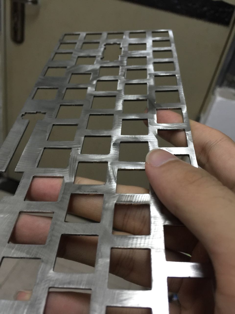
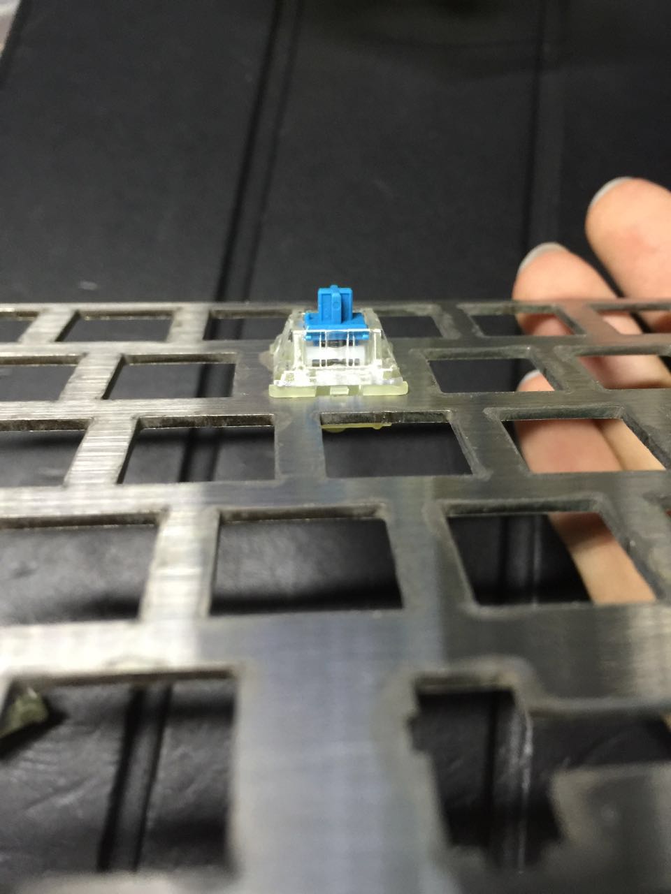
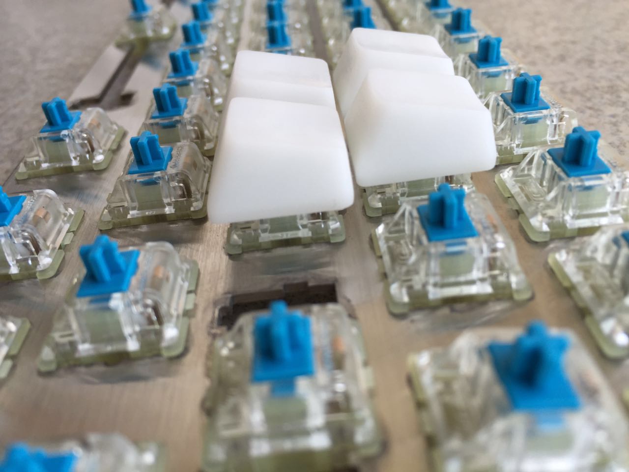
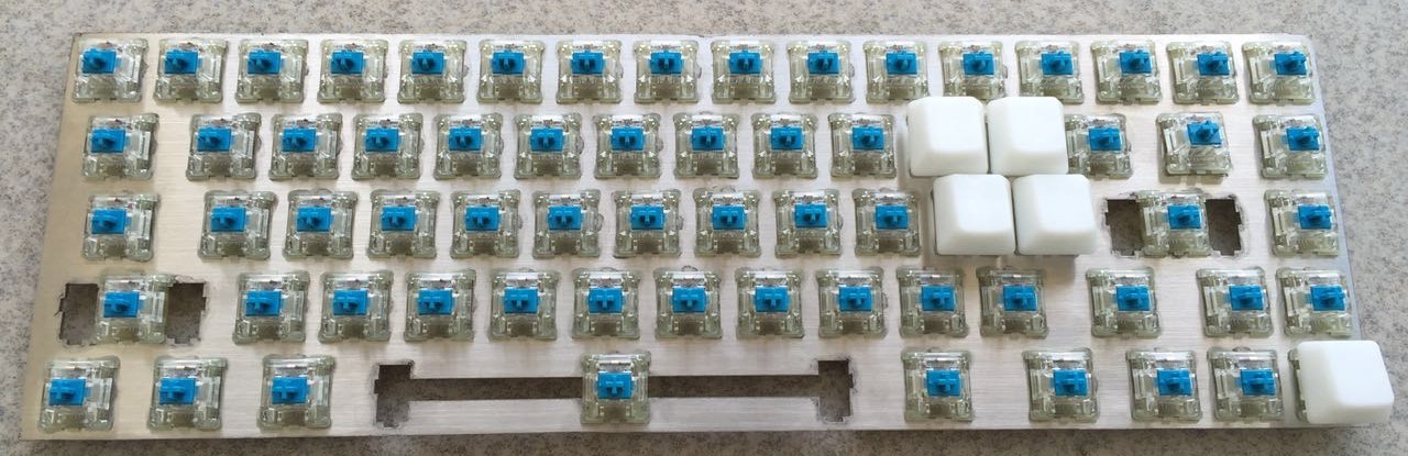
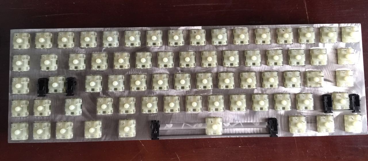
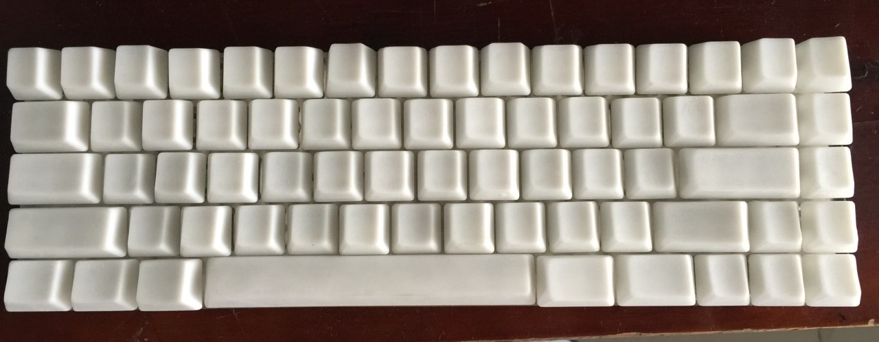
Since the keycaps are 3D printed, error may occur in spacing, and you may notice those alignment issues in each row. This is a common issue with 3D printing that I cannot help with. But don't worry since the final production would be using plastic injection molding, and we will make them as accurate as possible.
Bluetooth
My other sincere partner Yu Qianshan is in Jilin, China. He is currently messing with the Bluetooth stack and building our very first demo that would support Bluetooth 4.1 HID over GATT Profile (HOGP) with up to 10 simultaneous connections.
However, since TI doesn't provide the complete source code of their Bluetooth stack, we have to explore around to get the puppy running. Currently we have already ported a small SPP demo to our development platform. I think we are near to the goal.
Firmware
I'm designing the fundamental kernel of the firmware. My aim is to create a kernel that consumes the lowest power possible and provides the most significant latency optimization for real time response. Thus I decided to integrate an event driven kernel to our firmware. Specifically, I'm considering using the ultra-lightweight and lightening fast QP-nano framework that comes with a combination of cooperative and preemptive kernel and a state chart UML programming framework for state machine abstraction. This allows me using their awesome QM state chart design and code generation automation tool to build reliable and real time firmware.
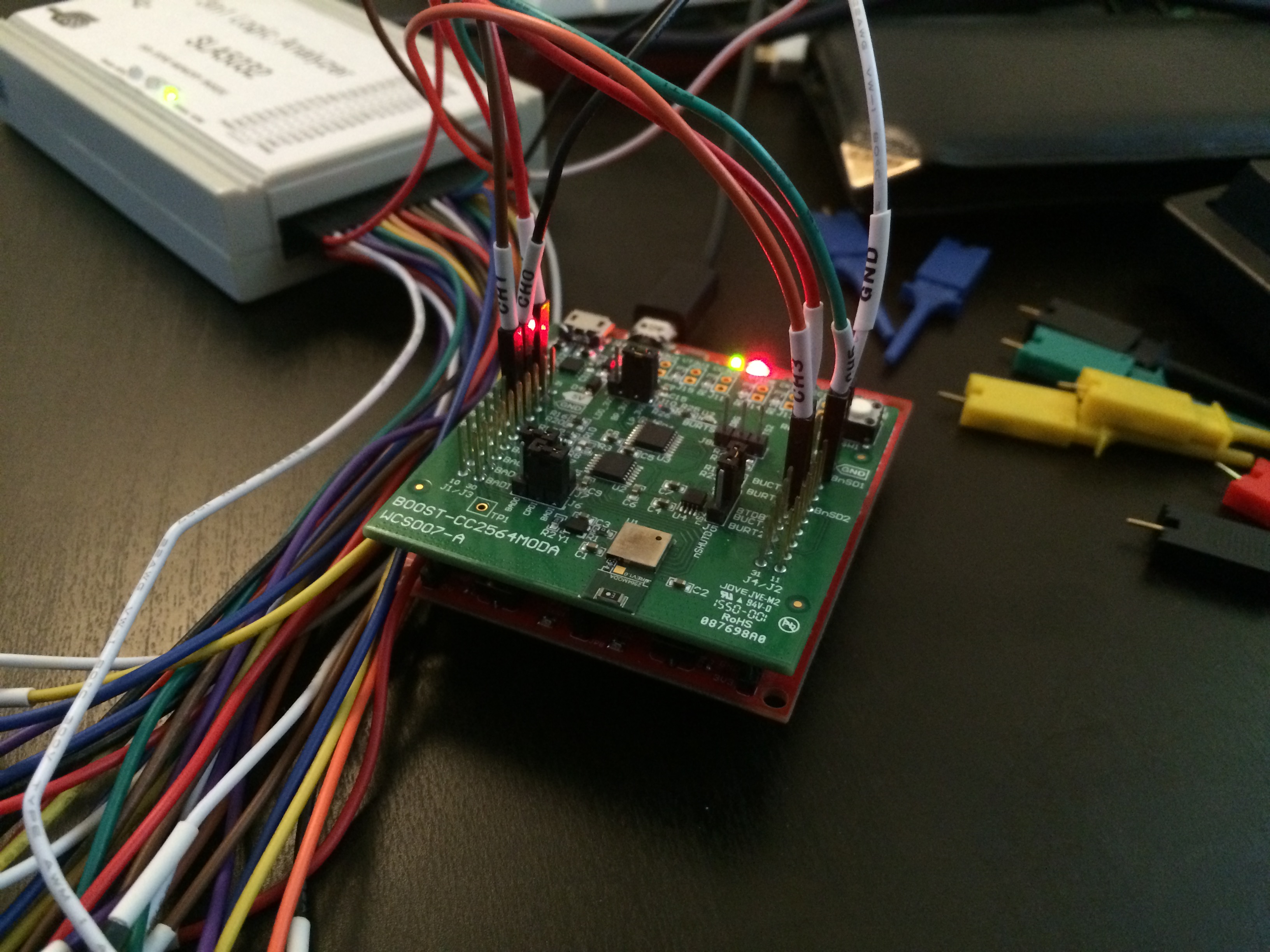
However this also means we have to rewrite most of the drivers to integrate with our state charts. I think this is good because the TI's "official" driver is a pile of GARBAGE! It looks exactly like written by some interns who have no idea what is good API and code design. Rewriting them means better code style, better organization and integrations, reduced redundancies and repetitions. But it may also be tragic to me since TI doesn't provide all its drivers with full source codes, like the CC2564 Bluetooth chip. This means I have to do A LOT OF reverse engineering to hack their object codes, and rebuild the portion we need. That's why you saw the crazy logic analyzer I was using in the photo above.
Therefore the whole firmware will be a very time consuming sub-project I will be working on for a very long time. I hope Yu can bring me some good news in the meanwhile so that we may have an idea of the whole system functioning.
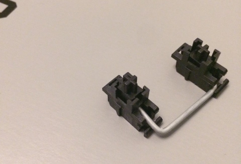
Matrix Scanner Chip
Oh I have to say I LOVE THIS CHIP! Its footprint is much smaller than I expected.
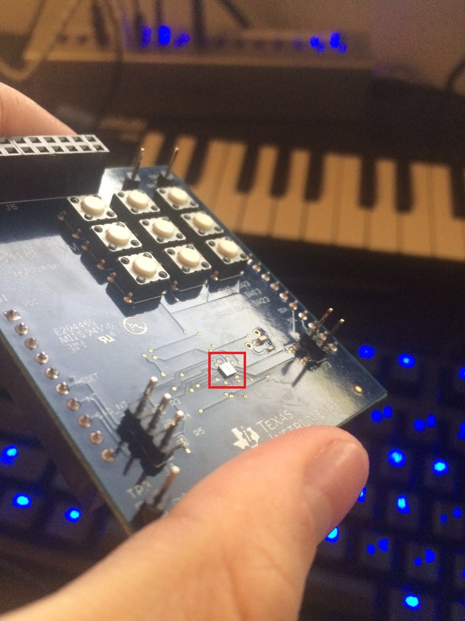
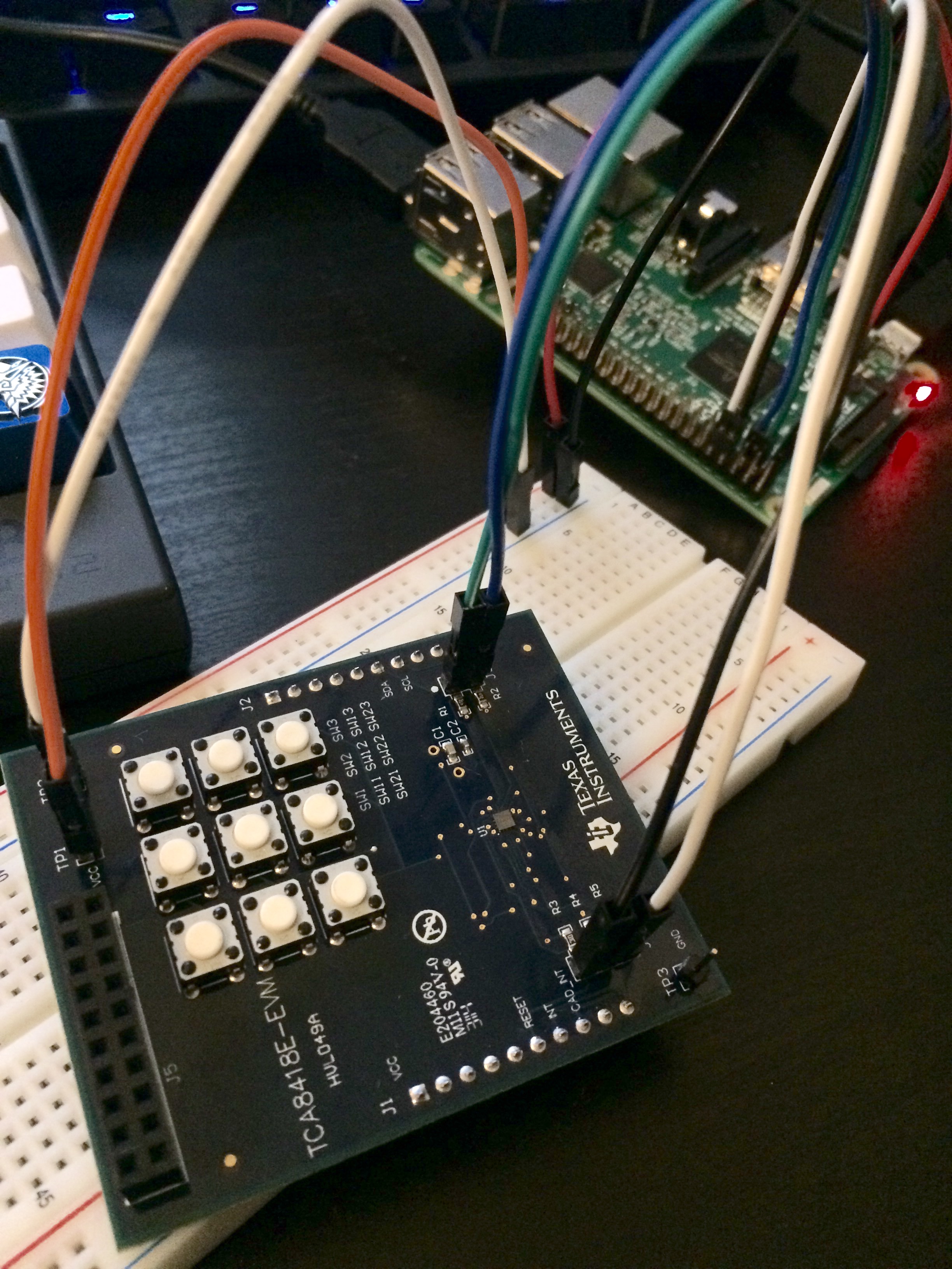
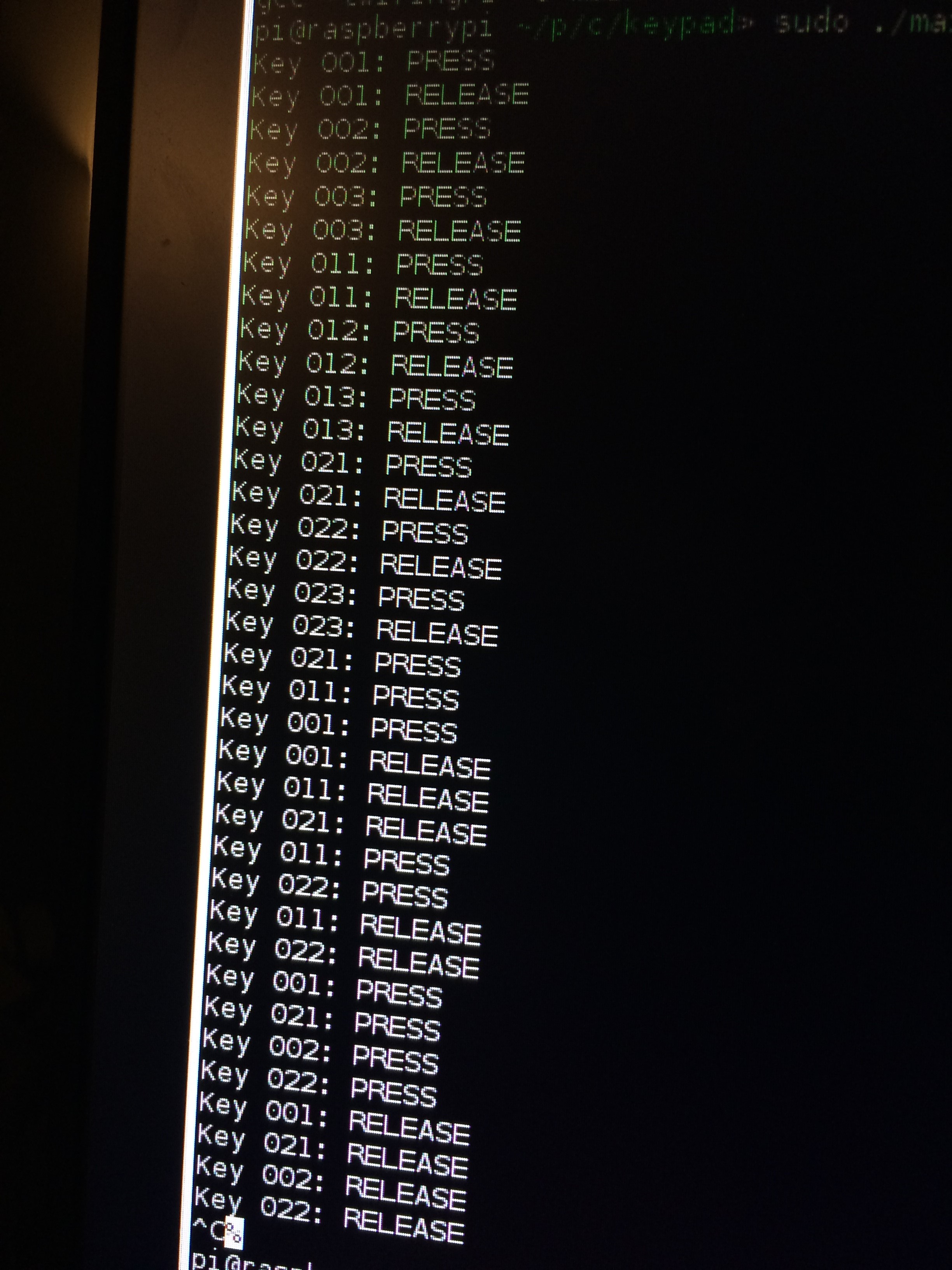
More importantly, it's AMAZINGLY powerful and easy to use. The I2C interface works like a charm. I had it tested on my Raspberry Pi, and everything worked in the first compilation!
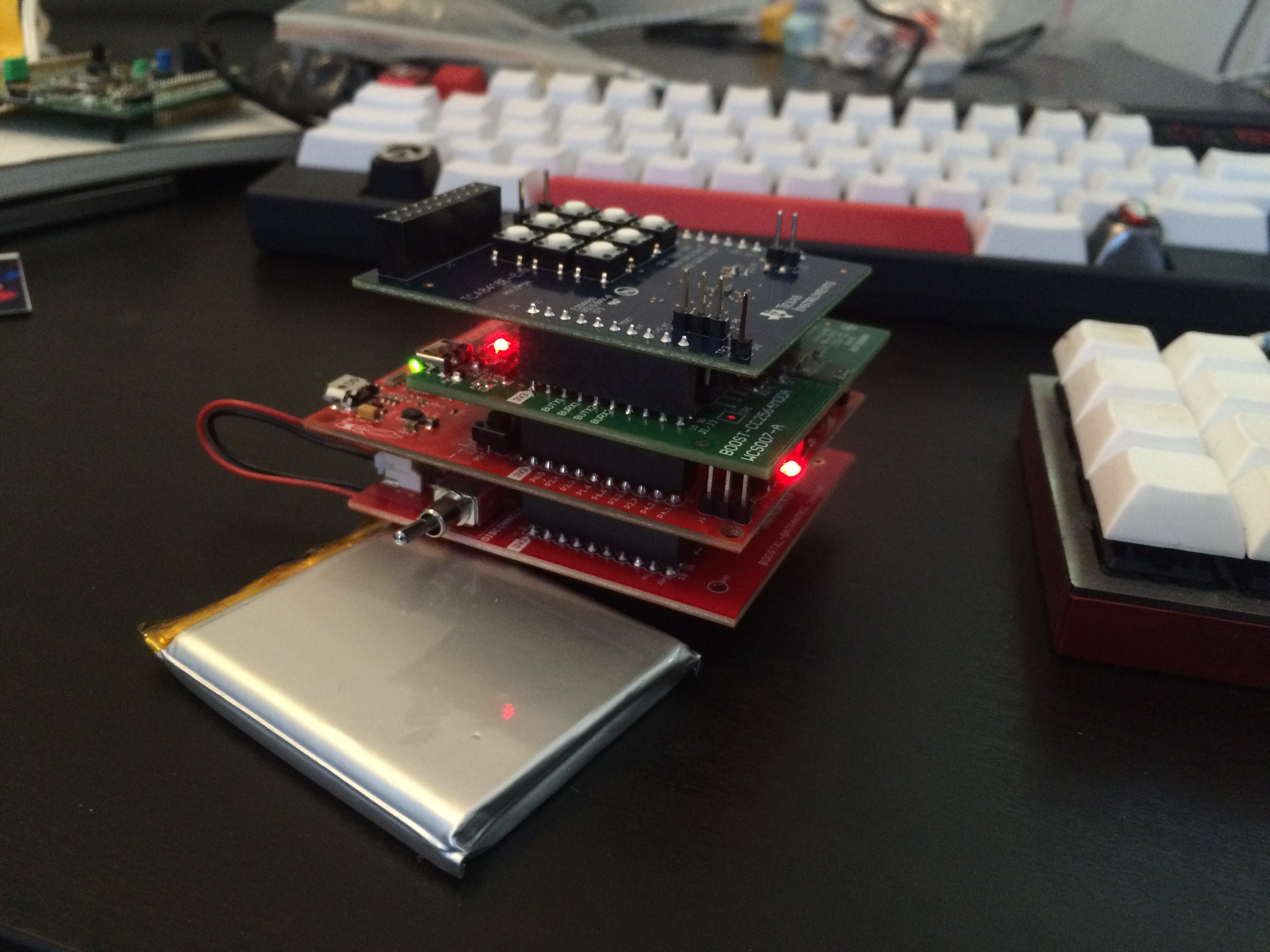
Power Pack
The power management is also from TI's chip. It supports smooth transition from USB power to battery power and vice versa. The battery will also be charged when connected to USB. Just look at all these TI BoosterPack stacked up! What a double sandwich!
LED PWM Chip
After communicating with Panasonic reps., the 288 channel chip was a joke, and we were limited to 144 channel instead. That's alright since we have the powerful I2C interface to handle multiple chips. What makes it difficult is that there's absolutely no stock on Earth for the 144 channel chip. This is probably because Corsair is eating up the supply of this specific chip. The reps. told me the general lead time would be 15-20 weeks. CRAZY!
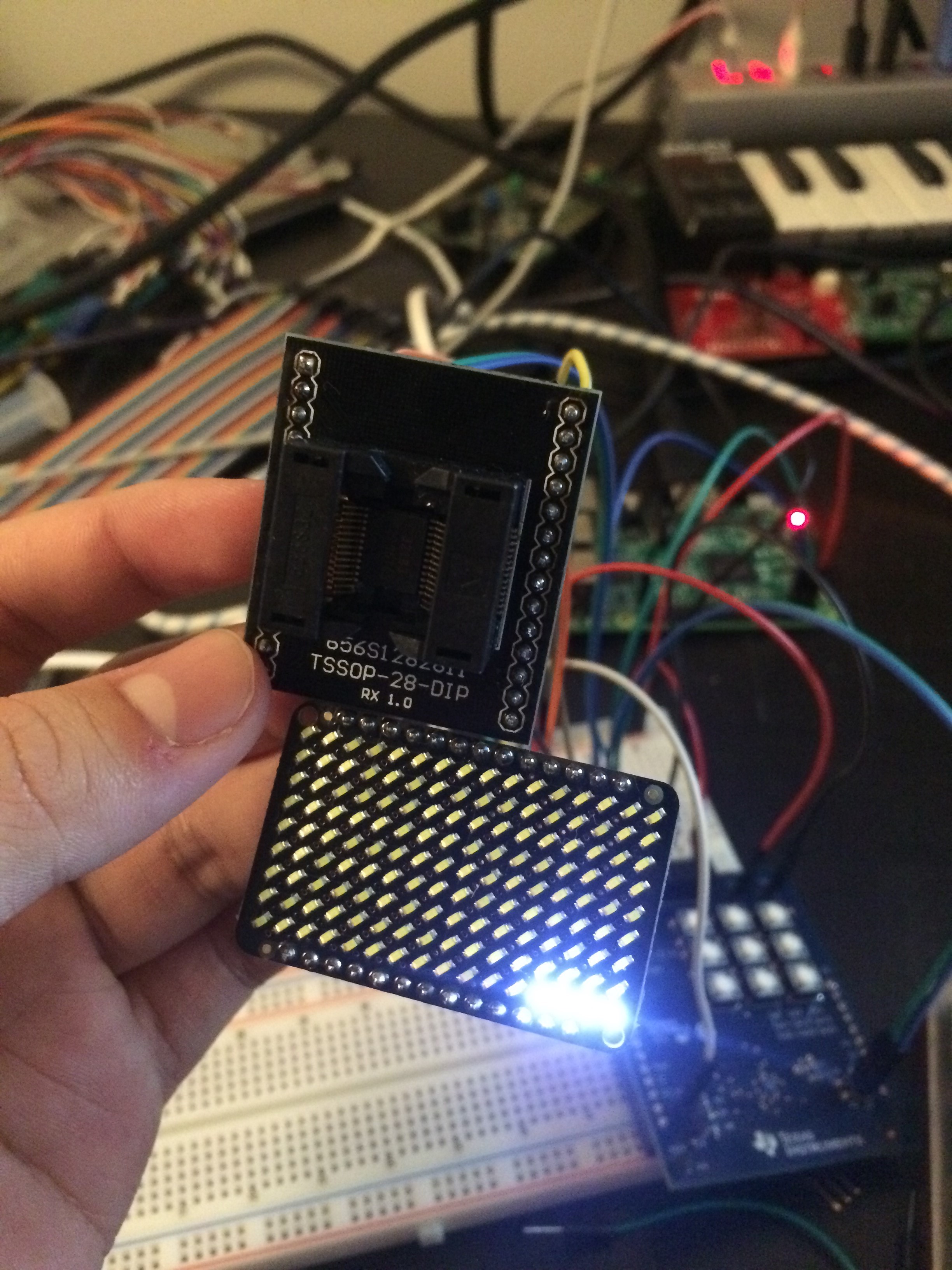
So instead of letting him order me samples for a quarter, I decided to use the weaker model ships from the same series that only has a total of 9x9 channels and provides a relatively prototyping friendly TSSOP package compare to the exclusive QFN SMD packages for other models in the same series. It has the exact same I2C interface like all the other models, so the code working on this model should also work on other models with some minor changes of the number of channels.
However, TSSOP is still too small for manual soldering. Thus I spent some time and found a nice test socket that can snap the pins on the chip and export them to solder friendly footprints. So I bought some of these sockets and made an adapter myself.
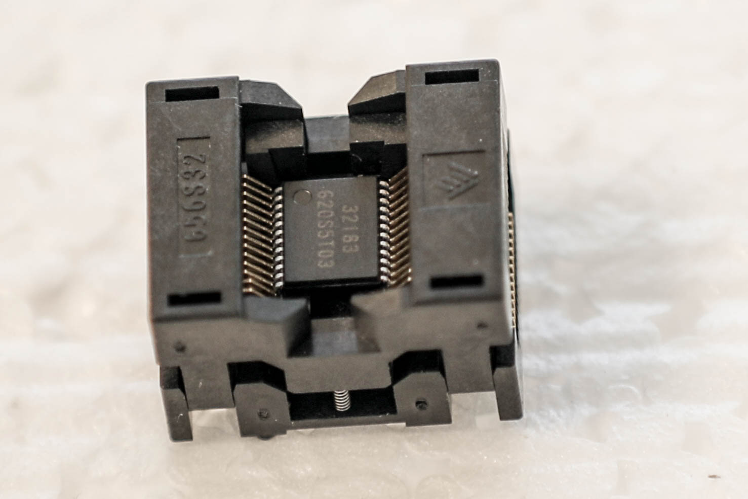
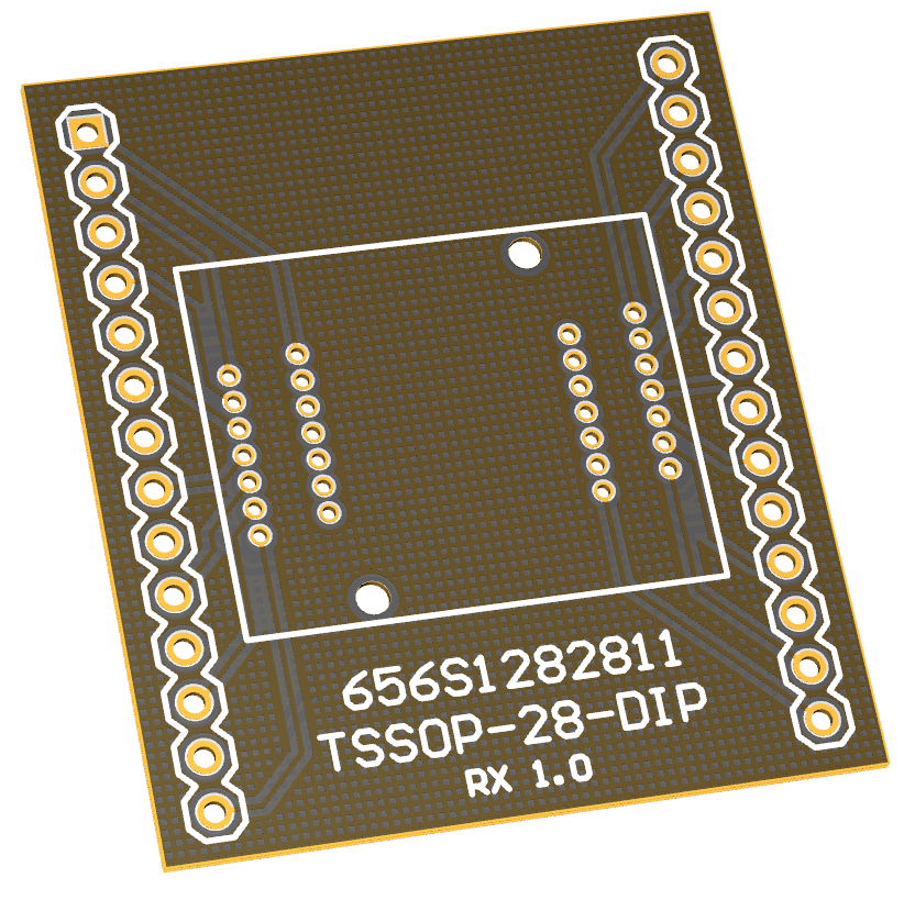
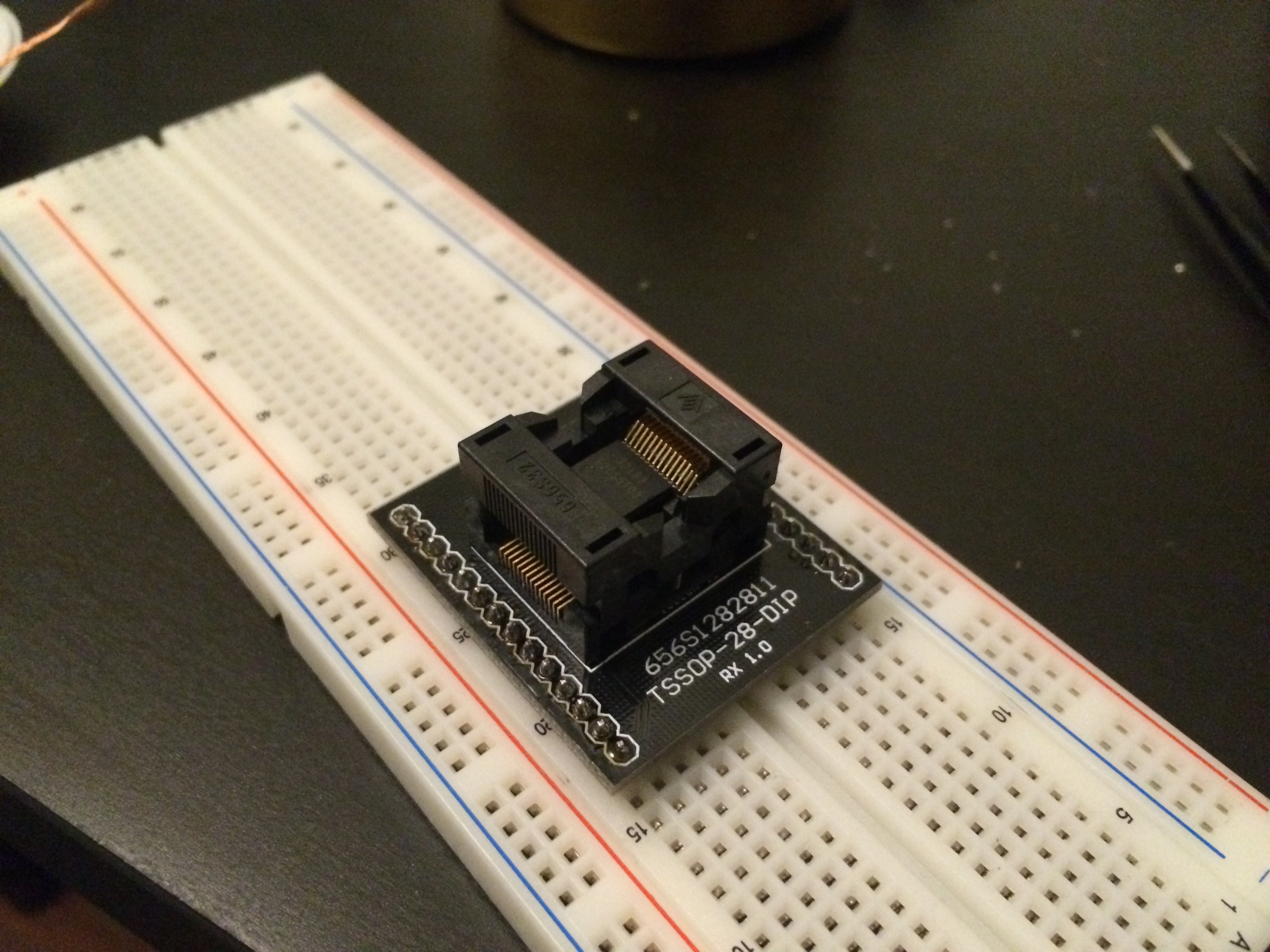
This way I can easily connect the chip with my development platforms. I may start testing this chip tomorrow, and would expect some more updates after that.
Update on 18/11/2016:
As promised, I tested my own adapter with the Panasonic LED PWM Matrix chip today. It took me a while to connect the wires on the breadboard since this chip is much more powerful than the key scanner chip. Anyway, I had it setup and everything worked fine so far. I can manually program it through the I2C interface from my Raspberry Pi, and light up any single LED on the matrix with any PWM level I choose.
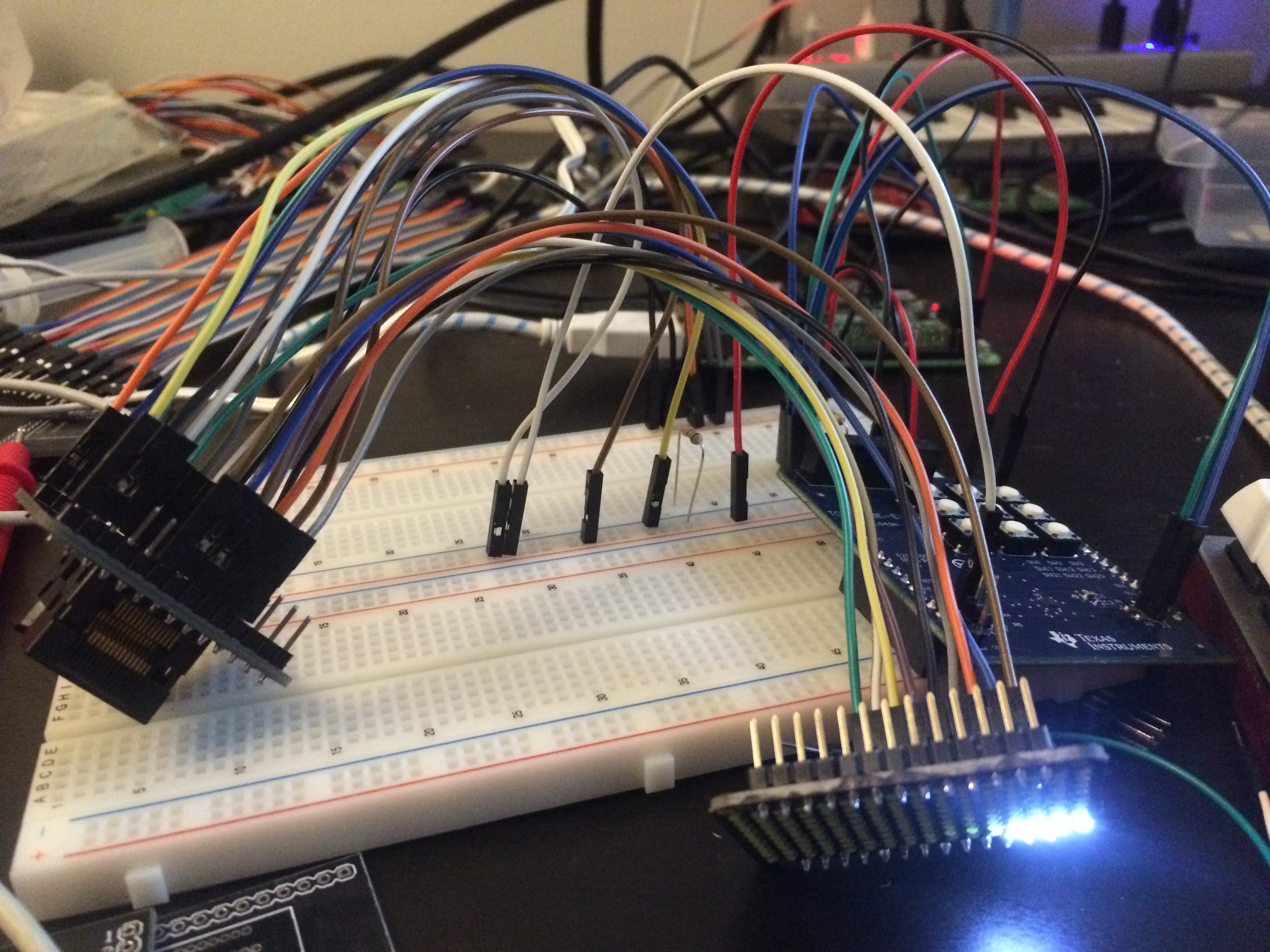
To clarify, I'm using an uni-color LED matrix board because I couldn't find a RGB 3-color independent channels LED matrix board online. But since RGB is just grouping every 3 LEDs together to create colors, I can simulate the underlining logic on the uni-color board as well.
Although nothing fancy to show you guys right now, this demo should still be a successful proof of concept to me. I will work on some eye candy demo during the weekend, and let's see what this puppy is capable of.
More to come...